Skip to content

Double Rainbow

With Abby's help, I have modified my code to calculate the screen mapping by applying masks to both the low and high frequency rainbow images. By then combining the low and high frequency mask, I can determine the location of the screen mapping. Below are the results of comparing predicted versus measured hue values using our double rainbow method.

It is still really bad. Here is the 3D image figure:

Most of the screen mapping is going to the top left corner. There is something weird going on with comparing hue values to generate our masks.

What's Next:

  • fix this stupid screen mapping
  • Clean up code and document everything better so that it can be used by the lab.

Starcraft Machine Learning

I am learning about the twitch (video streaming service that 'televises' Starcraft games) API service and how to interface with a stream so that I may use my Starcraft Win Predictor on live data.

I am also cleaning up the code so it is more useable for the a server.

This week I focused on designing the backend for the dynamic web app I'm developing. In my design, I tried to focus on the bare-bones functionality that I need to get the basic prototype working. I have never done dynamic web development before, so I spent a fair amount of time reading and looking into tutorials.

I picked a flexible, open-source frontend template that I really like, so I decided to start from there to choose the frameworks/languages I'll work with:  Javascript and .NET. I read several introductions to both to get some background, then some introductions to dynamic web dev (links posted soon).

After a fair amount of thought deliberation, and research into AWS' dynamic web development frameworks, here is the design I came up with for the dynamic backend:

explainED backend diagram
explainED backend

I also redesigned the schema for the user database to make it as simple as possible.

My tasks for the upcoming week are as follows:

  1. retrain the classifier and save the state_dict parameters
  2. learn about AWS Cognito and how it functions
  3. do some quick Javascript tutorials.
  4. create a nodeJS docker container for the template
  5. get the website template up and running locally
  6. make HTML button and form for entering a URL for analysis.


I attended a meeting on Monday with Annijka at Descartes and Nick at Dzyne where they discussed the current Descartes platform and the Wide Area Motion Imaging (Wami) data available.  The primary Wami data originates from hurricane Florence which encompassed half of the eastern US seaboard.  To minimize the problem, the intent is to focus on an Area of Interest (AOI) around Wilmington, NC with four or five samples taken along the path of destruction in Wilmington and nearby inland areas.  Descartes is also looking at data originating from southeast Asia and San Juan due to the differences in infrastructure between different nations.  Data is expected to be ready for Phase 2 kickoff.

I have also begun the "onboarding" process with the Descartes Platform which involves gaining access to the platform and working through the instructions and tutorials for using the platform.  We have a bi-weekly tag-up meeting scheduled for tomorrow at 2pm where further introductions will be made.

In other news, I have researched integrating a Google calendar into slack which will allow us to establish a consistent teleconference.  This should allow any lab member to join the set teleconference appointment each week without the need to deal with messy point-to-point calls and last minute coordination.  Regular teleconferences will be established on Tuesday from 11a-12p for any paper meeting and on Thursday 2p-3p for the weekly lab meeting.

We modified our code a bit, to use ResNet without the softmax layer on the end. We then did our 'over training check', by training on a minimal number of triplets, to ensure the loss went to 0:

We then tried a test with all of our data (~500 images), to see if our loss continued to decrease:

One thing we found interesting is that when we train with all of our data, the val_loss converges to the margin value we used in our triplet loss (in this example margin = 0.02, and in other examples where we set margin=0.2, val_loss -> 0.2).

We believe this could be troubling if you look at this equation for triplet loss (https://omoindrot.github.io/triplet-loss):

L=max(d(a,p)d(a,n)+margin,0)

It appears to me that the only way for L = margin is if the distance from the anchor to the positive is the exact same as the distance from the anchor to the negative, whereas we want the positive to be closer to the anchor than the negative.

Dr. Pless recommended that we visualize our results to see if what we are training here actually means anything, and to use more data.

We set up our data-gathering script on lilou, which involved installing firefox, flash, and selenium drivers. The camera that we were gathering from before just happened to crash, so we spent some time finding a new camera. We are currently gathering ~20,000 images from a highway cam that we'll use to train on.

After this we will visualize our results to see what the net is doing. However we are a bit confused on how to do this. We believe that we could pass a triplet into the net, and check the loss, but after that, how could we differentiate a false positive from a false negative? If we get a high loss, does this mean it is mapping the positive too close to the anchor, or the negative too far from the anchor? Do we care?

Is there some other element to 'visualization' other than simply looking at the test images ourselves and seeing what the loss is?


This may be a brief post because I'm home with a sick toddler today, but I wanted to detail (1) what I've been working on this week, and (2) something I'm excited about from a conversation at the Danforth Plant Science Center yesterday.

Nearest Neighbor Loss

In terms of what I've been doing since I got back from DC: I've been working on implementing Hong's nearest neighbor loss in TensorFlow. I lost some time because of my own misunderstanding of the thresholding that I want to put into writing here for clarity.

The "big" idea behind nearest neighbor loss is that we don't want to force all of the images in a class to project to the same place (in the hotels in particular, doing this is problematic! We're forcing the network to learn a representation that pushes bedrooms and bathrooms, or rooms from pre/post renovations to the same place!) So instead, we're going to say that we just want each image to be close to one of the other images in its class.

To actually implement this, we create batches with K classes, and N images per class (somewhere around 10 images). Then to calculate the loss, we find the pairwise distance between each feature vector in the batch. This is all the same as what I've been doing previously for batch hard triplet loss, where you average over every possible pair of positive and negative images in the batch, but now instead of doing that, for each image, we select the single most similar positive example, and the most similar negative example.

Hong then has an additional thresholding step that improves training convergence and test accuracy, and which is where I got confused in my implementation. On the negative side (images from different classes), we check to see if the negative examples are already far enough away from each other. If it is, we don't need to keep trying to push it away. So any negative examples below the threshold get ignored. That's easy enough.

On the positive side (images from the same class), I was implementing the typical triplet loss version of the threshold, which says: "if the positive examples are already close enough together, don't worry about continuing to push them together." But that's not the threshold Hong is implementing, and not the one that fits the model of "don't force everything from the same class together". What we actually want is the exact opposite of that: "if the positive examples are already far enough apart, don't waste time pushing them closer together."

I've now fixed this issue, but still have some sort of implementation bug -- as I train, everything is collapsing to a single point in high dimensional space. Debugging conv nets is fun!

I am curious if there's some combination of these thresholds that might be even better -- should we only be worrying about pushing together positive pairs that have similarity (dot products of L2-normalized feature vectors) between .5 and .8 for example?

Detecting Anomalous Data in TERRA

I had a meeting yesterday with Nadia, the project manager for TERRA @ the Danforth Plant Science Center, and she shared with me that one of her priorities going forward is to think about how we can do quality control on the extracted measurements that we're making from the captured data on the field. She also shared that the folks at NCSA have noticed some big swings in extracted measurements per plot from one day to the next -- on the estimated heights, for example, they'll occasionally see swings of 10-20 inches from one day to the next. I don't know much about plants, but apparently that's not normal. 🙂

Now, I don't know exactly why this is happening, but one explanation is that there is noise in the data collected on the field that our (and other's) extractors don't handle well. For example, we know that from one scan to the next, the RGB images may be very over or under exposed, which is difficult for our visual processing pipelines (e.g., canopy cover checking the ratio of dirt:plant pixels) to handle. In order to improve the robustness of our algorithms to these sorts of variations in collected data (and to evaluate if it actually is variations in captured data causing the wild swings in measurements), we need to actually see what those variations look like.

I proposed a possible simple notification pipeline that would notify us of anomalous data and hopefully help us see what data variations our current approaches are not robust to:

  1. Day 1, plot 1: Extract a measurement for a plot.
  2. Day 2, plot 1: Extract the same measurement, compare to the previous day.
    • If the measurement is more than X% different from the previous day, send a notification/create a log with (1) the difference in measurements, and (2) the images (laser scans? what other data?) from both days.

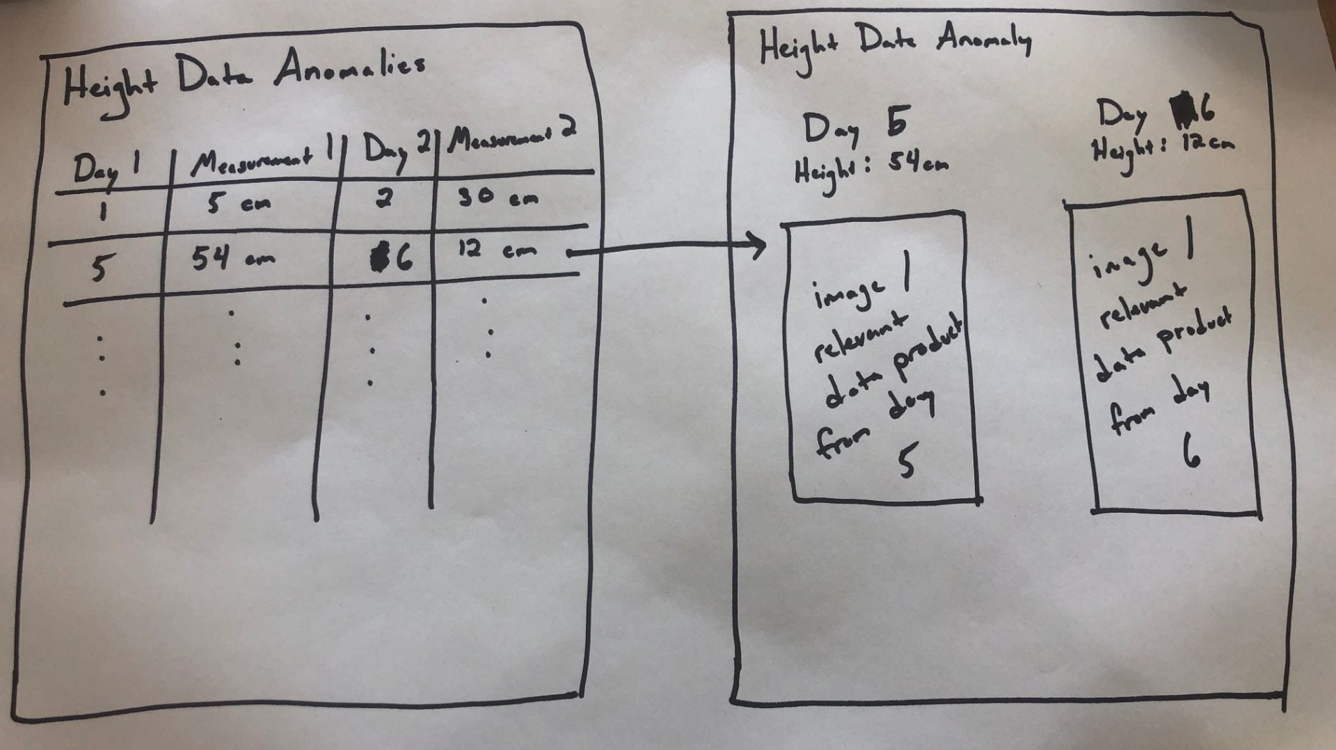
I'd like for us to prototype this on one of our extractors for a season (or part of a season), and would love input on what we think the right extractor to test is. Once we decide that, I'd love to see an interface that looks roughly like the following:

The first page would be a table per measurement type, where each row lists a pair of days whose measurements fall outside of the expected range (these should also include plot info, but I ran out of room in my drawing).

Clicking on one of those rows would then open a new page that would show on one side the info for the first day, and on the other the info for the second day, and then also the images or other relevant data product (maybe just the images to start with, since I'm not sure how we'd render the scans on a page like this....).

This would (1) let us see how often we're making measurements that have big, questionable swings, and (2) let us start figuring out how to adjust our algorithms to be less sensitive to the types of variations in the data that we observe (or make suggestions for how to improve the data capture).

[I guess this didn't end up being a particularly brief post.]

Leaf length/width pipeline

The leaf length/width pipeline for season 6 is running on DDPSC server. This is going to be finished in next week.

The pipeline currently running finds the leaves first instead of plots. So I rewrote the merging to fit this method.

Leaf Curvature

I'm digging into the PCL (Point Cloud Library) to see if we could apply this library to our point cloud data. This library is originally developed on C++. There is an official python binding project under development. But there are not too many activities on that repo for years. (Also there is a API for calculate the curvature is not implemented on this binding.) So should we working on some point cloud problems on C++? If we are going to keep working on the ply data, considering the processing speed for point cloud and the library, this seems like a appropriate and viable way to work with.

Or, at least for the curvature, I could implement the method used in PCL with python. Since we already have the xyz-map. Finding the neiberhood could be faster than on the ply file. Then the curvature could be calculated with some differential geometry methods

PCL: http://pointclouds.org/

PCL curvature: http://docs.pointclouds.org/trunk/group__features.html

Python bindings to the PCL: https://github.com/strawlab/python-pcl

Reverse Phenotyping

Since the ply data are too large (~20 TB) to download(~6 MB/s). I created a new pipeline to find only the cropping position with ply file. So that I can run this on NCSA server and use those information to crop the raw data on our server. This is running on NCSA server now and I'm working on the cropping procedure.

I'm going to try Triplet loss, Hong's NN loss and Magnet loss to train the new data and do what we did before to visualize the result.

Read ahead for a video! Game changer...

In my last post, I mentioned that my current error function and method of finding "lit" centroids was set up in a way that did not make the total error 0 when the camera and light locations were correct. This was due to the fact that I was finding centroids that were near the light, thus causing the error to never be 0. In an attempt to better understand if this kind of error was the cause of poor optimization results, I did the quick & dirty method of forcing the surface normals of centroids deemed to be "lit" to be such that those centroids would actually reflect rays from the camera directly to the light position instead of bouncing them to some area around the light position.

Forcing all "lit" centroids

The error in the dot product of the surface normals when the camera & light are int he correct locations is 0, which is what we want. Then, I fixed the light location at many different locations, and for each location, optimized for the camera location - the following movie shows a plot of the light/camera locations for each light location on a grid, colored by the final error achieved by the optimization function. This video demonstrates this:

light-camera-animation_forced (Converted)-2mpzu0k

For this I get the following results:

minimum error = 2.8328e-6
maximum error = 0.0072
best light location (min error) = [120, 30, 55]
best camera location (min error) = [95.5, 78.8, 110.5]

Trying to optimize for both using this method

If I just force these surface normals, and then try to optimize for both the camera & light, it finds both locations beautifully (as it should), with an error of 2.2204e-16, finding the locations to be:

light location = [115, 30, 57.499]
camera location = [100, 80, 110]

So, this tells us that there is a fundamental problem with the was we are defining what centroids are 'lit', a problem which can be I think avoided by looking at the image of the glitter taken when a point light source is shone on it. This way we can find the 'lit' pieces without defining such a threshold of 'angular difference in surface normals'. The down-side to this, we are getting closer and closer to our original method of optimization, and subsequently, calibration...

2

This post has several purposes.

FIRST: We need a better name or acronym than yoked t-sne.  it kinda sucks.

  1. Loosely Aligned t-Sne
  2. Comparable t-SNE (Ct-SNE)?
  3. t-SNEEZE? t-SNEs

SECOND: How can we "t-SNEEZE" many datasets at the same time?

Suppose you are doing image embedding, and you start from imagenet, then from epoch to epoch you learn a better embedding.  It might be interesting to see the evolution of where the points are mapped.  To do this you'd like to yoke (or align, or tie together, or t-SNEEZE) all the t-SNEs together so that they are comparable.

t-SNE is an approach to map high dimensional points to low dimensional points.  Basically, it computes the similarity between points in high dimension, using the notation:

P(i,j) is (something like) how similar point i is to point j in high dimensions --- (this is measured from the data), and

Q(i,j) is (something like) how similar point i is to point j in low dimension.

the Q(i,j) is defined based on where the 2-D points are mapped in the t-SNE plot, and the optimization finds 2-D points that makes Q and P as similar as possible.  Those points might be defined as (x(i), y(i)).

With "Yoked" t-SNE we have two versions of where the points go in high-dimesional space, so we have two sets of similarities.  So there is a P1(i,j) and a P2(i,j)

yoked t-SNE solves for points x1, y1 and x2,y2 so that the

  1. Q1 defined by the x1, y1 points is similar to P1, and the
  2. Q2 defined by the x2,y2 points are similar to P2 and the
  3. x1,y1 points are similar to x2,y2

by adding this last cost (weight by something) to the optimization.  If we have *many* high dimensional points sets (e.g. P1, P2, ... P7, for perhaps large versions of "7") what can we do?

Idea 1: exactly implement the above approach, with steps 1...7 talking about how each embedding should have Q similar to P, and have step 8 penalize all pairwise distances between the x,y embeddings for each point.

Idea 2: (my favorite?).  The idea of t-SNE is to find which points are similar in high-dimensions and embed those close by.  I wonder if we can find all pairs of points that are similar in *any* embedding.  So, from P1... P7, make Pmax, so that Pmax(i,j) is the most i,j are similar in any high-dimensional space.  Then solve for each other embedding so that it has to pay a penalty to be different from Pmax?  [I think this is not quite the correct idea yet, but something like this feels right.  Is "Pmin" the thing we should use?]


1

In last week, I do an experiment on comparing embedding result between Npair loss and Proxy-loss, for testing yoke-tsne.

Npair loss is a popular method which try to push point in different class away and pull point in same class close (like triplet loss) , while the proxy loss just assign a specific place for each category and just push all points in this category in this place. I expect to see this difference on embedding result by yoked tsne.

In this experiment, which is same to last two, CAR dataset is split into two part, and I just train our embedding on the first part (by Npair and Proxy loss) and visualize it.

This result is as following (left part is Npari loss and right part is Proxy loss):

Here is the original one:

Here is the yoked one:

The yoked figures shows some interesting thing about those two embedding method:

First, In Npair Loss result, there are always some points in different class in cluster while are not in Proxy Loss. Those points should be very similar to the cluster, and the reason why the Proxy loss doesn't have such points is that the proxy fixed all points in one class to same place, so those points was moved into their own cluster. Next step, I will find corresponding image for those points.

Second, they are more clusters mixed up in proxy loss, maybe its shows that proxy play a bed performance in embedding.

Third, the corresponding clusters is in some place and comparing to the original one, the local relationship doesn't change too much.


2

Last week I decided to pursue the optimization route to try and find the light & camera locations simultaneously. This post will focus on the progress and results thus far in the 3D optimization simulation!

In my simulation, there are 10,000 centroids all arranged in a grid on a plane (the pink shaded plane in the image below. There is a camera (denoted by the black dot) and a light (denoted by the red dot). I generate a random screen map - a list of positions on the monitor (blue shaded plane) such that a position on the monitor corresponds to a centroid. I use this screen map and the centroid locations to calculate the actual surface normals of each centroid - we will refer to these as the ground truth normals.

Then, I assume that all of the centroids are reflecting the point light (red dot), and calculate the surface normals of the centroids under this assumption - we will refer to these as the calculated normals. The centroids which are considered to be "lit" are those whose ground truth normals are very close to their calculated normals (using the dot product and finding all centroids whose normals are within ~2 degrees of each other - dot product > 0.999).


This visualization shows the centroids which are "lit" by the light and the rays from those centroids to their corresponding screen map location. As expected, all of these centroids have screen map locations which are very close to the light.

To optimize, I initialize my camera and light locations to something reasonable, and then minimize my error function.

Error Function

In each iteration of the optimization, I have some current best camera location and current best light location. Using these two locations, I can calculate the surface normals of each lit centroid - call these calculated normals. I then take the dot product of the ground truth normals and these calculated normals, and take the sum over all centroids. Since these normals are normalized, I know each centroid's dot product can contribute no more than 1 to the final sum. So, I minimize the function:

numCentroids - sum(dot(ground truth normals, calculated normals))

Results

No pictures because my current visualizations don't do this justice - I need to work on figuring out better ways to visualize this after the optimization is done running/while the optimization is happening (as a movie or something).

Initial Light: [80 50 50]
Initial Camera: [50 60 80]

Final Light: [95.839 80.2176 104.0960]
Final Camera: [118.3882 26.4220 61.7301]

Actual Light: [110 30 57.5]
Actual Camera: [100 80 110]

Final Error: 0.0031
Error in Lit Centroids: 0.0033

Discussion/Next Steps

1. Sometimes the light and camera locations get flipped in the optimization - this is to be expected because right now there is nothing constraining which is which. Is there something I can add to my error function to actually constrain this, ideally using only the surface normals of the centroids?

2. The optimization still seems to do less well than I would want/expect it to. It is possible that there is a local min that it is falling into and stopping at, so this is something I need to look at more.

3. It is unclear how much the accuracy (or lack thereof) affects the error. I want to try to perturb the ground truth surface normals by some small amount (pretend like we know there is some amount of error in the surface normals, which in real life there probably is), and then see how the optimization does. I'm not entirely sure what the best way to do this is, and I also am not sure how to go about measuring this.